
Low voltage light switch
Low voltage light switch
Low voltage light switch

Low voltage light switching
How to program Lutron Energy Saver Node Panel

I call a QSM unit .That QSM unit is used
program. RF units or RF switches which are radio frequency .Lutron has their
own own frequency .that they use they've had that battery so nobody else can
use it.

Now when you use the hardwired system which this here is hardwired. In the QSM is hardwired into the unit and so are your switches.

As soon as you connect the power to it
your unit will already pick up anything that is already hardwired. So, since
that saying that as soon as you push that button because it's already
programmed in, the light is on zone 4.
We can program the switch to do other
lights too if we want to.
How to program the RF unit?
So we'll turn that one off and we will start by. this is already controlled into it. We have to program the remote into the QSM unit and then Program the RF switch into the plane itself.

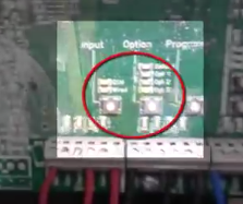
So this is how you program the RF switch
into this QSM unit. First of all you press the program button, you see it there
hold it until you hear a beep, then you go to your remote. You push your off
button till you hear three beeps. Now you have to take it out of program mode. So you press the program button again on your QSM till you hear beep then it's
exited.
Now we need to program our switch to
which zone we want it to in the panel and we can do multiple zones. You can do
more than one.
So first of all, we start by these are
your zones here 1, 2, 3 & 4.

Now first of all you go to your RF button and press the on and off button simultaneously till you hear a beep.

Your QSM mode did not come on the light when you try to wire. You try to put your remote into the panel.
So what you have to do now?
Are you have to go to the to the QSM unit
and program it to the panel first before you can program the switch?
and how you do that is?
Note: You only have to exit program mode for
the pico IR switch if you need to program the QSM unit.
Take another program mode for the switch.
you can see it's back on wired. so now what you have to do is push program on
the QSM till you hear the beat.
Note: This QSM programming is only needed if the QSM LED on the panel did not light up when you tried to program to pico switch.
Your latest come On will be flashing. Then we set the option and it's on option 3 we'll set it to default. You’ll see a flashing on default. Then you will hold the button until you default button stays on. Press option button till default LED stay on and your hear a beep.
Then you do find out which zone you want
this RF switch to go on. you're going to make it a couple different zones. You should be first going to hit the zone 3.

You will notice that the
zones that are programed should now be flashing.
By hitting both buttons at the same time and then go to hit Zone 1 and hit both buttons at the same time the off and on. Then that you know which zones you want to come on. you can go back to the unit the switch push the off and on button again until you hear the beep and .Then this switch will be turned on zone 1 and zone 3.
So they should both come on at once when you push the on button. So then it's programmed. for that and then you'll turn it off and now you've got your other wired Switch . You did it before that turns on zone 4 and that switch here should turn on 1 & 3.
Hard Wiring your lab
-You will need your tools –
-18/3 and 14/2 wire
-Wire connectors
-Staples
-Various Lutron Products.
You will need to do some hard wiring
before you can program the Lutron Panel.
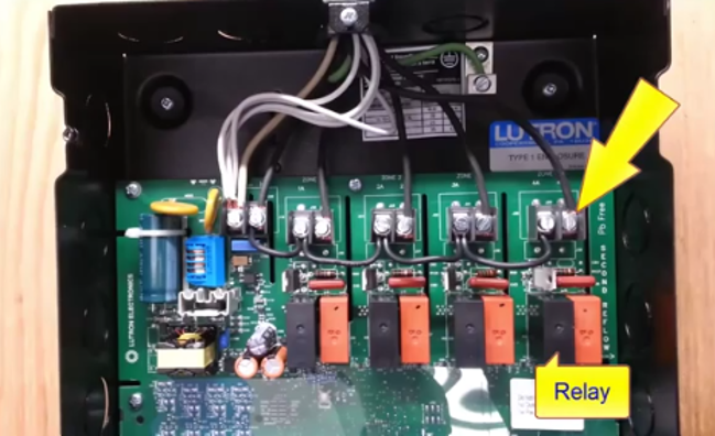
Now I am going to talk a little bit about how exactly you're going to wire up lab based on the programming. They'll find one of these units, the Lutron energy saver node located between two cubicles. That means each unit has a capability of having four persons working on it . The actual 120 volt connections will happen in this box up.

Here you see it has black and white wires.
so you have your neutral your black and you have basically four lines or four
loads that this unit can handle. so there's one
Load there on the black and white the
third load. On the other black and white and the fourth load on the other black
and white the black and white on the far left is the actual feed. That goes
into the panel that feeds the unit. You should've removed the safety guard to
indicate where you actually feed this main panel.

Note: This unit has been wired this way
for learning purposes. Actual wiring of this unit would be different in real
life situations.
As you can see it has one place where it
feeds the line and then from here you be able to you have jumpered each one of
the loads so that basically one feed will feed all the lights for your lab.
That
has been done to reduce the amount of connections we need. But in the Real
world you can bring individual circuits to each one of these screws. So you
would bring a circuit into there from first breaker, a second breaker, third
breaker, fourth breaker and then ask route of loads will go out on the other
side,
as you can see that wire goes up and it
gets connected to the blacks.
We have added all the neutrals together. So all the neutrals are connected into one spot to simplify, we're bringing in only one circuit and basically parallel connections to all of them. We were being in two pieces of wire to this panel from our cubicle.

You'll bring the wire that goes to your
light and make a connection bring it into your plastic connectors or you are
familiar from last intake and make your connections to the black and white. Pick up the ground obviously.

The other wire you'll be bringing. Here
will be the Low-voltage connection. that will be connected to three wires now.
you'll notice that we have different color wires. There we have blue, black, red
and black on this side. This is to indicate the difference between the multiple
zones.
Each one of these wires is connected to a
particular type of connection on the panel.

I removed some of the wires. you can see
where the wires are connected. The first wire is connected to something called
twenty volts and then is connected to IR and then common. So basically as you
can see where the black R is the first fourth and sixth connection. So we're
not using OCC with the occupier sensor or daylight sensor or switch. we are
just using the twenty IR and common.
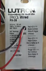
If you look at the hardwired switch,
you'll be using which is this one here. it has three wires on it and you'll
Notice if we were to look at it that the red is twenty the black is common and
your white is your single.
If you follow our wires they are hooked
up one, two, three and one, two, three is the same connection down in this area
here.

Keep that in mind that they are in order
hooked up down below. The same way they are hooked up above the wire.
You'll be using to hook up your low voltage switch will be 18/3 wire. Very similar to what we use for doorbell.

But this one has three conductors- a red,
a black and a white.
You'll also need more to make the
connection between the wires and your switch.
You should be using the smallest wire
connect that you have.

As you can see we have a large good for
Number 12 and larger we have the 14 gauge wire. Wire connects for you to use. But you try using these orange ones that are made for smaller gauges. Such as-
this 18/3 wire. to make your connections between the wire and the switches in
the shop. We are using currently the orange ones, each person will work in
their own cubicle.
We will place a low voltage switch in a
switch box mounted at 52 inches just like we learned in mass in peg for regular
switches and you'll also need a round box for a light. so you will need a
keyless a light bulb. the 14/2 we'll go from the light bulb to the unit on the
back of this plywood. If you're working in other cubicles, you may need to go
from your light all the way across and come along stapling your wire to go to
your control panel. So on total, we will have four 14/2 is coming from two
cubicles back to our panel.
Note: The low voltage wire will also go
to the Lutron panel from the other cubicals.
The
low voltage wire from your switch will
also go from a switch box To your panel in the lower section.
Your 14/2 will go for the light and your
18/3 low voltage wire will come for the hardwired switches. Let's go over where we're going to run the
wires. We're Going to use 18/3 gauge wire sort of on the switch box is mounted
at 52 inches. We are running the wire inside a box. Since this is low voltage
wire, technically according to code you really do not need a box. You can use a
plaster ring or you can just fasten it to the drywall making a hole so that's
the advantage.
Another advantage of low voltage wiring the code
book does not require for you to need to have a box. But we are going to use one for the labs. So we have it in the box. We've stripped some
wires back and we run it down across. Our studs still going to need your
staples. If it's a new installation to keep it from being damaged. I'm coming
in front and being screwed by drywall screws. So you still need your staples
come across through the studs and you're going to bring your wire into the section which I showed on below and why are
your three wires into there. You're also going to do your 120 volts.
Note: In real life you could start your
feed here and send the power down the white conductor and return on the black
from the Lutron panel.
Basically here you do Need a box base
for your light. The connection is from there going across and up and into the
four by four, four by eleven, sixteenths box up top through your grounds.
and I'm going to hook up my black and my white
to my far right. your partner will hook
up to the next one and so on - you have four persons using this this unit there.
This was a real life situation, you would most likely send the power down. the white wire back at the round octagon box where The keyless is and when the wire comes in to this panel.

You would hook up the white wire to one
of the terminations here.
Let's say the left screw then when the
relay closes.

or
basically your infrared single. So the same connections have to be made to your
panel and as I mentioned the first one will be your twenty. First black wire in
this case, the second black wire will be your IR and the last one is your
common.
Because this takes it up to the board. That has 20 IR common and that is repeated for all three loads. You don't have
to strip very much, you just need a little bit. A little Mount- there
quarter-inch any longer and then you'll have the wire sticking out. there's a
possibility of shorting out to the back of the box. that same rule applies to
when you're hooking up your actual 120 volts. so this wire is going back to the
actual light. as you can see the black wire has been stripped correctly. the
white is a little long and you don't want that because in case it shorts out
the back of the box. you'll have it that short so that 120 volt is Fed from the
panel comes up. when it's turned on it, go to the black wire. it also gives it
neutral and it will go to your life that has been hooked up so what- that means
is basically when you hit the switch, your light will come on as we talked
about in the programming. but we also want you to program your remote control
switch so that it turns on your light and your other partners like beside you.
Go to a hardwired switch the other person
will hook up to these three blue wires third person to these three black wires
and four person to these other three red wires.
You will need to push the button on QSM
to program your Pico switch when programming.
Everything will be coming up top due to the
fact that this is a Learning Lab. We are missing some of the rules where this
cable comes in front of 2x4. if it was in the real world will be passing all
these cables through holes And inside studs and this we mounted inside a wall.
we wouldn't have all the external boxes also our connections such as done
outside.

Here would actually be done inside the unit at
the proper terminals. But once again for learning purposes we have extended
these wires outside so that we can remove install and remove and install again. Once you've wired up all your wires and the rest of your partners have done. The same we are basically ready to power up the unit so that the students can
start programming their individual zones. so once you all four you have
completed your and we will power up the unit for you and you can start
programming quick reminder to everybody that once you're done you're supposed
to remove all the wires are you installed. Do not back out all the screws
completely, just loose enough loose enough. That you can remove the wires and
remove all your 18/3 and 14/2 wires from the top of the boxes and the bottom to
fasten and unfasten these wires. You should be using a small terminal driver. Anyone caught using anything bigger than this will be deducted marks, this is
the proper tool for the proper job.


.png)